Sunday 25 May 2014
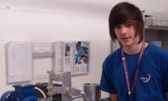
Mark Laird – Apprentice Challenge 2014

For a number of successful years, NNL has participated with Gen2 providing a working environment and long term opportunities for many young people. Gen2 is a joint venture training company formed as an apprentice engineering and technology training provider.
Working alongside industry partners such as NNL, Gen2 delivers high quality apprentice training in the West Cumbrian region. NNL engineering apprentices Mark Laird and Declan McAvoy have recently taken part in the Gen2 apprentice challenge launched around Cumbria as part of National Apprentice Week.
Mark describes his experience for uknnl.com.
Beam Engine – Mark Laird
I worked in a team of six as part of the apprentice challenge to design, research, construct and present a visual demonstration piece for children/young adult’s aged between eight and 18. The task was to incorporate all aspects of engineering we use in the Gen2 centre. This included mechanical/mechanical design, electrical/electrical design, welding, fabrication and pipe fitting. The final product had to demonstrate the diversity of apprentice trades and how they can be applied into different tasks in and out of the workplace.
The team began by brainstorming ideas and we came up with the beam engine idea. We then went on to research how we would prepare the engine. From our research we found that the beam engine had to be designed in great detail for it to work. Angles and lengths had to be worked out correctly otherwise the piston would either not have a great enough stroke or not run straight.
We overcame this challenge by using ‘SolidWorks’, a 3D design programme, to give us a virtual representation of whether or not it would operate correctly. I spent a week or so developing our idea into something which we could see working on the computer. This meant having to calculate the stroke of the piston dependant on the size of the followers, the positioning of holes and the size of the cam. Once it was all working on screen, we began production.
The process began with the machining of main components for the engine. This includes all of the followers and rods, the cam and the vertical beam that the whole assembly pivots around. These were cut out on the CNC Mill. However, we did come across interesting challenges along the way, the main one being that the CNC machine could not cut out the shapes we had designed as they were too big.
To overcome this issue, I had to redesign the parts to make them work while still being able to be cut out on the mill. This took a lot of trial and error to get it to work. When we achieved our objective, the new smaller size seemed to work better than before. When we had all of the parts machined, we removed the burrs from them and filed them to a nice finish.
With the main parts produced, we could begin producing other components on the centre lathe at Gen2. The new parts being machined were brass fittings, nylon legs, washers, perspex cylinder, aluminium tank, hand wheel, piston, piston rod and the aluminium shafts. These components were also designed on SolidWorks and had to be machined with a small tolerance to make sure the engine would work.
Once these parts had been machined, the base plate was the final piece to be produced. We initially decided to cut out a 10mm thick piece of mild steel with 500mm x 500mm dimensions. However, this had to be changed as we were using a larger motor with a variable speed control. So we changed the design of the base plate so that it was a 6mm thick plate of mild steel that and 600mm x 600mm.
The base plate was cut out on the guillotine and we cleaned up the edges, applied chamfers and began to drill holes to enable the components to be bolted in. We also had to attach the motor, speed control and bearings. Locations for the holes were marked on the plate and we drilled them out on the radial arm drill.
We were nearly there as once the holes were drilled we just needed to assemble all of the parts together. The components cut out on the CNC Mill were joined together with the brass inserts and the nylon washers. We put the nylon legs onto the base plate so that it would stand off the table. We had to bolt down all of the bearings to the base plate along with the motor.
The team had to make sure that the alignment was correct for the belt to drive the gear. Once the driving end was set up, we bolted down the main beam and cylinder making sure that the piston was inside the cylinder and that the stroke was correct. It ran as we expected from the design we did up front. We connected the cam to the drive shaft and the cam follower.
This was it. All of the parts were assembled and the engine was working. We piped up the cylinder to a tank of water and turned on the motor. The belt drove the gear which in turn drove the shaft. This drove the cam, which drove the followers that acted around a central pivot creating a linear motion that forced the piston up and down within the cylinder, pumping the water in and out of the tank.
The Beam Engine was entered into the competition at the Apprentice Challenge Final at Energus in Workington. Other competitors came from Lakes College, Energus, Carlisle and Furness. Out of all the demonstrative pieces ours came first. We were judged by respected people from the local community and enjoyed demonstrating our model to the visitors that day.
